Electrical interference from patient movement, infusion pumps or other equipment (e.g. HFOV)
Ensure the lower electrode is placed well below the lower ribs to prevent respiratory interference.
Ensure that the filter mode is selected.
Complex too large – rate displayed is too high
Check lead II selected.
Observe for T-wave size and for artefact which will lead to elevated rates due to increased pick-up of ‘complex’.
Alter lead selection until normal complex seen.
Decrease the size/gain.
Twelve-Lead ECG Recording (Figure 3.1)
The twelve-lead ECG is used to gain a three-dimensional picture of the electrical activity of the heart from right to left, superior to inferior and anterior to posterior. A total of 10 electrodes are required to record the standard ECG: one on each wrist and ankle and six across the precordium (Drew et al. 2004) (see Table 3.2).
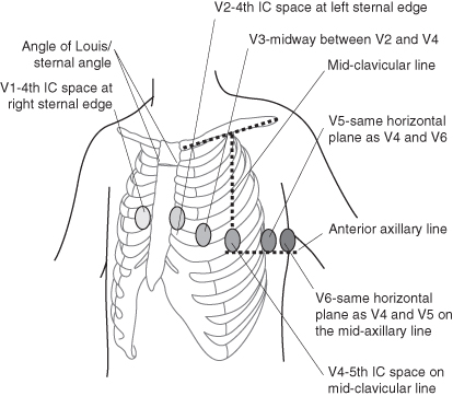
Table 3.2 Lead placement for a twelve-lead ECG recording
| Chest leads | Limb leads |
| There are six chest leads to site: V1: right 4th intercostal space, two spaces below the angle of Louis V2: left 4th intercostal space, two spaces below the angle of Louis V3: this is found between V2 and V4 V4: left 5th intercostal space, in the mid-clavicular line V5: found between V4 and V6 V6: left 5th intercostal space, in the mid-axillary line | There are four limb leads, one of which is neutral: aVR: A bony point between heart and right hand; around the wrist joint is ideal (red) aVL: A bony point between heart and left hand; around the wrist joint is ideal (yellow) aVF: A bony point between heart and left foot; the ankle/anterior superior iliac spine is ideal (green) Neutral: A bony point between heart and left foot; the ankle/anterior superior iliac spine is ideal (black) |
Atrial Wire ECG Recordings
In certain conditions following cardiac surgery it is of use to record an atrial wire ECG. This is achieved by connecting one of the temporary atrial pacing wires to the V1 lead and running a recording. This is most useful when the child is tachycardic and there is a need to analyse the relationship between the P wave and the QRS complex.
Invasive Pressure Monitoring
Haemodynamic monitoring has two distinct components: electronic equipment, and a fluid-filled tubing system (McGhee and Bridges 2002).
The electronic equipment has three elements (Scales 2010):
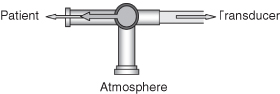
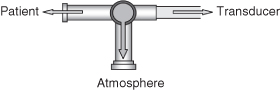
Connecting either an arterial catheter or central venous catheter to a fluid-filled tubing system allows the pressure in the vessel to be transmitted through the tubing to a transducer. The transducer links the tubing to the electrical system and converts the mechanical pressure wave from the blood into an electrical signal (McGhee and Bridges 2002). The signal is transmitted along a pressure cable to the monitor where the signal is amplified and displayed as a waveform (Scales 2008).
To ensure that accurate monitoring data is displayed the transducer must be calibrated to zero pressure. This is performed as follows:
Maintaining Line Patency
There is considerable discussion regarding the use of heparin to maintain the patency of invasive monitoring lines, and studies in adults have identified that there is no difference in line patency when comparing the use of heparin infusions with plain 0.9% sodium chloride infusions (Hall et al. 2006; Kannan 2008; Tuncali et al. 2005). Ultimately, local policy will determine its use or non-use. The mechanism for continuously infusing through invasive monitoring lines is usually through the use of a 50 ml syringe and an infusion pump. Infusion rates tend to be adjusted according to age (an important consideration in the fluid-restricted neonate or young child) with rates from 0.5 ml/hr for the neonate to 3 ml/hr for the adolescent. If there are concerns regarding line patency, the volume of the infusate may be increased, however, this increase must be accounted for in the child’s fluid intake.
Arterial Lines and Monitoring
Arteries have a similar structure to veins and consist of three layers:
- Inner coat: the tunica interna (intima) is composed of a lining of endothelium which is in contact with the blood, a basement membrane and a layer of elastic tissue called the internal elastic lamina.
- Middle coat: the tunica media is usually the thickest layer and consists of elastic fibres and smooth muscle.
- Outer coat: the tunica externa (adventitia) consists of mainly elastic and collagenous fibres.
Thanks to the structure of the middle layer, arteries have two major properties: elasticity and contractility. When the ventricles of the heart contract and eject blood into the large arteries they have the capacity to expand and accommodate the extra blood volume. When the ventricles relax, the elastic recoil of the arteries forces the blood on through the systemic and pulmonary circuits respectively.
The contractility of the artery arises from its smooth muscle which is arranged both longitudinally and circumferentially around the lumen. Sympathetic branches of the autonomic nervous system innervate this muscle.
When there is sympathetic stimulation the smooth muscle contracts, squeezing the wall around the lumen, which narrows the vessel causing vasoconstriction. Conversely, when sympathetic stimulation is removed the smooth muscle fibres relax, allowing the size of vessels lumen to increase causing vasodilation. Vasodilation is usually a consequence of the inhibition of vasoconstriction. The contractility of arteries also occurs as a protective mechanism to reduce bleeding, a process known as vascular spasm.
Key Difference between Veins and Arteries
- Arteries lie deep in the tissue and are protected by muscle.
- Veins have valves to prevent the back flow of blood; arteries do not.
- The muscular arterial wall maintains patency of the lumen even when blood pressure is low.
- There may be an occasional aberrant artery, which is located superficially in an unusual place. This should not be mistaken for a vein. A common place for this to occur is in the antecubital fossa region.
Types of Artery
- Elastic (conducting) arteries.
- Muscular (distributing) arteries.
- Arterioles.
- Anastomoses.
Elastic Arteries
Large arteries are referred to as elastic or conducting arteries. Examples include:
- Aorta.
- Brachiocephalic.
- Common carotid.
- Subclavian.
- Vertebral.
- Common iliac.
The walls of elastic arteries are relatively thin in proportion to the diameter, and the tunica media contains more elastic fibres and less smooth muscle. As the heart contracts and relaxes, so the rate of blood flow tends to be intermittent. When the heart contracts (systole) and forces blood into the aorta the walls of the elastic arteries stretch to accommodate the surge of blood and store the pressure energy. During relaxation of the heart (diastole) the walls of the elastic arteries recoil to create pressure, moving blood forward in a more continuous flow.
Muscular Arteries
Medium-sized arteries are called muscular or distributing arteries. Examples include:
- Axillary.
- Brachial.
- Radial.
- Intercostal.
- Splenic.
- Mesenteric.
- Femoral, popliteal, tibial.
In these vessels the tunica media contains more smooth muscle than elastic fibres. These arteries are capable of greater vasoconstriction/vasodilation, allowing adaptation of the volume of blood to suit the needs of the structure being supplied. The walls of these arteries are relatively thick, mainly due to the large amounts of smooth muscle fibres.
Arterioles
Arterioles are very small, almost microscopic arteries which deliver blood to the capillaries. The structure of the arterioles varies according to how close they are to the arteries from which they branch. Those closest to the feed artery have a tunica interna similar to of the main arteries, a tunica media composed of smooth muscle with very few elastic fibres and a tunica externa composed of mostly elastic and collagenous fibres. Conversely, arterioles nearest to the capillaries consist of little more than a layer of endothelium surrounded by a few scattered muscle fibres. Changes in the diameter of arterioles can significantly affect blood pressure.
Anastomoses
Most areas of the body receive arterial supply from the branches of more than one artery. In such areas the distal ends of the vessel unite. The junction of these vessels is known as an anastomosis. This allows for an alternative blood supply to continue after damage to one of the supplying vessels, termed collateral circulation. (Arteries that do not anastomose are known as end arteries. Occlusion to an end artery will cause damage to the organ being supplied.)
Sites for Arterial Line Placement
The site chosen for arterial line insertion will depend on the clinical condition of the child and the experience of the practitioner undertaking the procedure. Commonly used sites are detailed in Table 3.3.
Table 3.3 Common sites for arterial line insertion
| Site | Advantages | Disadvantages |
| Radial artery | Easy to identify and cannulate due to superficial location. Accessible during most surgery. Dual circulation to the hand. Easy to immobilise. | High complication rate. Small artery requiring small catheter. Higher rate of occlusion due to thrombus formation. Nerve trauma during insertion. Increased artefact due to small catheter size. |
| Brachial artery | Large accessible vessel. Collateral circulation present. Less incidence of artefact. | Difficult to immobilise. Nerve damage from haematoma formation/traumatic insertion. |
| Femoral artery | Useful in shocked patient when unable to palpate other peripheral pulses. Large vessel – larger catheter may be used. Can be used for prolonged periods of time. | Difficult to immobilise. Difficult to keep site clean. Haematoma formation during insertion. |
| Axillary artery | Large vessel – larger catheter may be used. Collateral circulation present. Useful in patients with peripheral vascular disease. Reduced incidence of artefact. Accurate reflection of blood pressure. | Cerebral air embolism. Difficult to cannulate. Difficult to immobilise or secure site. Nerve damage. |
| Dorsalis pedis artery | Useful when other vessels unavailable. Dual circulation present. | Poor vessel for haemodynamic monitoring. Difficult to immobilise or secure site. Small vessel – small catheter. Greater risk of thrombosis formation. |
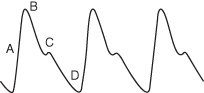
Physiology of the Arterial Pressure-Pulse Wave (Arterial Waveform) (Figure 3.4)
Left ventricular ejection results in the creation of a pressure wave and blood flow into the systemic arterial system. Pressure waves move at a rate of 10 m/s while blood flows at a rate of 0.5 m/s, therefore the pressure wave is transmitted to the peripheral arteries more rapidly and precedes actual blood flow. The waveform displayed on the monitor is relative to the phases of the cardiac cycle (see Chapter 4).
Figure 3.4 A simple arterial waveform.
From Teasdale, D (2009) Physiological Monitoring in Dixon et al (2009) Nursing the Highly Dependent Child or Infant: A Manual of Care. Reproduced with permission from John Wiley and Sons, Ltd.
Stay updated, free articles. Join our Telegram channel

Full access? Get Clinical Tree


