CHAPTER 7 Invasive Hemodynamic Monitoring
I. INVASIVE HEMODYNAMIC MONITORING BASICS
A. Concepts
B. Types of Monitoring Systems
1. Fluid-filled system attached to water manometer ( Fig. 7-1)
2. Fluid system with transducer, amplifier, and monitor ( Fig. 7-2)
3. Fiberoptic monitoring systems ( Fig. 7-3)
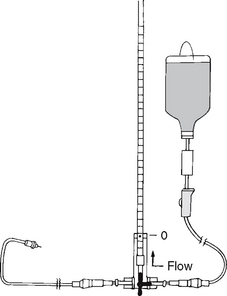
FIGURE 7-1 The stopcock is turned to fill the manometer to 25 cm H2O.
(From Roberts, J., & Hedges, J. [2004]. Clinical procedures in emergency medicine [4th ed.]. Philadelphia: Saunders.)
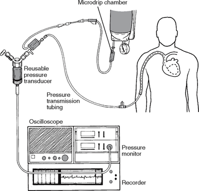
FIGURE 7-2 A fluid system of pulmonary artery pressure monitoring coupled with electronic instrumentation.
(From Darovic, G. O. [2004]. Handbook of hemodynamic monitoring [2nd ed.]. Philadelphia: Saunders.)
C. Pressure Monitoring System Components
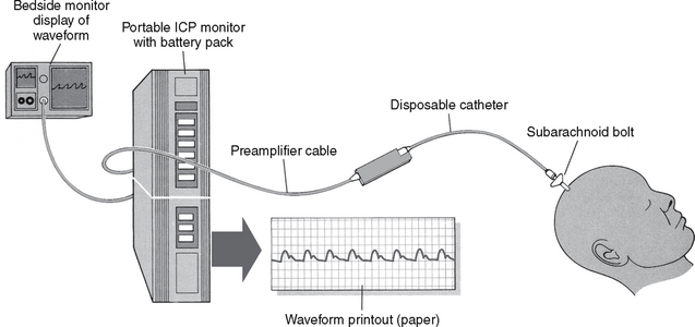
1. Catheter: provides access to patient’s vessels/brain for monitoring pressure
3. Rigid pressure tubing (for fluid-filled transducer system): optimizes physiologic signal transmission
4. Flush device with capillary restrictors: keeps system patent by allowing a continuous flow of solutions through line
5. Dead-end caps (nonvented): maintain sterility of stopcock ports
6. Transducer: senses physiologic pressure signals and converts them to an electrical signal with proportionate changes
7. Monitor and amplifier: creates readable signals, filters out unwanted “noise,” and displays waveform on oscilloscope
8. Flush solution: keeps line patent
9. Pressure-infuser bag or cuff: capable of providing 300 mm Hg pressure
D. Obtain Accurate Data
The clinician must take measures to ensure that the data obtained from invasive monitoring systems are accurate and reflective of the patient’s physiologic status. Box 7-1 identifies the characteristics of a reliable monitoring system. Other variables to consider are patient position, height of the transducer, zero referencing, and dynamic response testing.
Box 7-1 CHARACTERISTICS OF A RELIABLE MONITORING SYSTEM
The system should be as simple as possible. Extra stopcocks and manifolds decrease the fidelity of the monitoring system and increase the risk of fluid leak, microbial line contamination, and air bubble collection.
The bores of monitoring catheters should be no smaller than 18 gauge or 7 French. Small bores result in overdamping.
All connecting tubing should be of low compliance (stiff) and no longer than 3 to 4 feet. Low-compliance tubing is identified on packaging as “monitoring tubing.”
Tubing connectors should be tight. Use Luer-Lok connections, and inspect frequently for fluid leaks.
The catheter and connection tubing must be patent. Use a continuous-flush device for cardiovascular pressure monitoring, and inspect frequently to see that the pressure bag is inflated to 300 mg Hg. Routinely fast flush the monitoring systems of hypercoagulable patients.
The system must be free of air bubbles or clots. Even pinpoint air bubbles decrease the fidelity of monitoring systems.
Keep the connecting tubing away from areas of patient movement. Jostling of tubing results in an externally induced whip artifact.
From Davoric, G. O. (2004). Handbook of hemodynamic monitoring (2nd ed.). Philadelphia: Saunders.
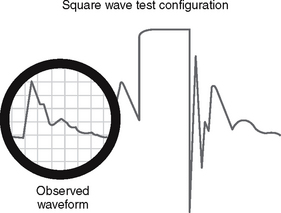
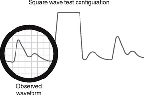
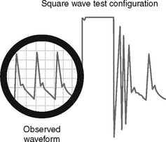
1. Dynamic response testing: a means to assess the transducer’s ability to accurately reproduce variations in the patient’s vascular pressures
Box 7-2 DYNAMIC RESPONSE TESTING (SQUARE WAVE, FREQUENCY RESPONSE TESTING) USING THE FAST FLUSH SYSTEM
From Davoric GO (2004). Handbook of hemodynamic monitoring (ed. 2). Philadelphia: Saunders.
Overdamped System
Intervention: To correct for the problem:
1. Check for the presence of blood clots, blood left in the catheter after blood sampling, or air bubbles at any point from the catheter tip to the transducer diaphragm and eliminate these as necessary.
2. Use low-compliance (rigid), short (less than 3-4 ft) monitoring tubing.
3. Connect all line components securely.
