Assisting with Diagnostic Imaging
Learning Objectives
1. Define, spell, and pronounce the terms listed in the vocabulary.
2. Apply critical thinking skills in performing the patient assessment and patient care.
3. Identify the principal components of radiographic equipment.
4. Describe the cassette and film image receptor system and explain its function in radiography.
9. List and describe imaging modalities that do not involve x-rays.
10. Explain the patient preparation guidelines for typical diagnostic imaging examinations.
11. Outline the general procedure for assisting with an x-ray examination.
12. Summarize guidelines for scheduling multiple diagnostic procedures.
Vocabulary
angiocardiography (an-je-o-kahr-de-og′-ruh-fe) Radiography of the heart and great vessels using an iodine contrast medium.
angiography (an-je-og′-ruh-fe) Radiography of blood vessels using an iodine contrast medium.
angioplasty (an′-je-o-plas-te) An interventional technique in which a catheter is used to open or widen a blood vessel to improve circulation.
anteroposterior (AP) (an-tuhr-o-pos-ter′-e-ohr) A frontal projection in which the patient is supine or facing the x-ray tube.
aortogram (a-or′-ti-gram) Radiography of the aorta using an iodine contrast medium.
arteriography (ahr-ter-e-og′-ruh-fe) Radiography of arteries using an iodine contrast medium.
arthrogram (ahr′-thro-gram) Fluoroscopic examination of the soft tissue components of joints with direct injection of a contrast medium into the joint capsule.
axial projections Radiographs taken with a longitudinal angulation of the x-ray beam; sometimes referred to as semiaxial projections.
bucky A moving grid device that prevents scatter radiation from fogging the film.
cathartics Laxative preparations.
computed tomography (CT) A computerized x-ray imaging modality that provides axial and three-dimensional scans.
contrast media Radiopaque substances used to enhance the visibility of soft tissues in imaging studies.
coronal plane The plane that divides the body into anterior and posterior parts.
coulombs per kilogram (C/kg) The international unit of radiation exposure.
dosimeter A badge for monitoring radiation exposure of personnel.
embolization An interventional technique in which a catheter is used to block off a blood vessel to prevent hemorrhage.
fluoroscopy (floo-ros′-kuh-pe) Direct observation of an x-ray image in motion.
frontal projection A radiographic view in which the coronal plane of the body or body part is parallel to the film plane; AP or PA.
Gray (Gy) The international unit of radiation dose.
intravenous urogram (IVU) Radiographic examination of the urinary tract using intravenous injection of an iodine contrast medium.
latent image Invisible changes in exposed film that become an image when the film is processed.
lateral projections Radiographic views in which the sagittal plane of the body or body part is parallel to the film.
lower gastrointestinal series Fluoroscopic examination of the colon, usually using rectal administration of barium sulfate as a contrast medium; also called a barium enema.
magnetic resonance imaging (MRI) An imaging modality that uses a magnetic field and radiofrequency pulses to create computer images of both bones and soft tissues in multiple planes.
myelography (mi-uh-log′-ruh-fe) Fluoroscopic examination of the spinal canal with spinal injection of an iodine contrast medium.
NPO Nothing by mouth, from the Latin nil per os.
nuclear medicine An imaging modality that uses radioactive materials injected or ingested into the body to provide information about the function of organs and tissues.
oblique projections Radiographic views in which the body or part is rotated so that the projection is neither frontal nor lateral.
phosphors (fos′-fors) Fluorescent crystals that give off light when exposed to x-rays.
posteroanterior (PA) A frontal projection in which the patient is prone or facing the x-ray film or image receptor.
rad The conventional unit of radiation dose.
radiograph An x-ray image.
radiographer A person qualified to perform radiographic examinations.
radiography The process of taking diagnostic images using x-rays.
radiologist A physician who specializes in medical imaging or therapeutic applications of radiation.
radiolucent (ra-de-o-loo′-suhnt) Pertaining to a substance that is easily penetrated by x-rays; these substances appear dark on radiographs.
rem The conventional unit of radiation dose equivalent.
roentgen (R) (rent′-gen) The conventional unit of radiation exposure.
sagittal plane The plane that divides the body into right and left parts.
Sievert (Sv) (se′-vuhrt) The international unit of radiation dose equivalent.
sonography (suh-nog′-ruh-fe) An imaging modality that uses sound waves to produce images of soft tissues; also called diagnostic ultrasound.
tracers Radioactive substances administered to patients for nuclear medicine imaging procedures.
transverse plane The plane that divides the body into superior and inferior parts.
upper gastrointestinal (UGI) series Fluoroscopic examination of the esophagus, stomach, and duodenum using oral administration of barium sulfate as a contrast medium.
Scenario
Sara Elwood, CMA (AAMA), is employed by Metro Urgicenter, an urgent care clinic in an urban setting. Metro is staffed around the clock and sees patients with urgent problems that are not immediately life-threatening. Facilities at the center include an x-ray department where films of the spine and the extremities are taken to evaluate injuries for possible fractures. Chest films also are taken to aid the diagnosis of patients with respiratory complaints. The center’s staff physicians read the x-ray films as they are taken. Afterward, the films are sent to a local hospital for formal interpretation by a radiologist. Sara often assists David Swain, the radiographer, by preparing patients for x-ray examinations and processing the films. Sometimes she is responsible for sending the films to the hospital for interpretation and then filing them when they are returned. Sara is in the process of helping the clinic switch to electronic medical records, which will make the transmission of radiology results much more efficient. When a patient is sent to some other facility for special imaging studies, Sara makes the arrangements and provides the patient with a preliminary explanation of the procedure.
While studying this chapter, think about the following questions:
Physicians have been using x-ray images for more than 100 years to examine the internal structures of the body. The fascinating field of medical imaging now includes a wide variety of diagnostic imaging methods. This chapter provides an overview of imaging modalities and introduces you to radiography. Emphasis is placed on x-ray examinations, because these are the procedures most commonly performed in the medical assistant’s practice setting.
Basic Principles of Radiography
Radiography
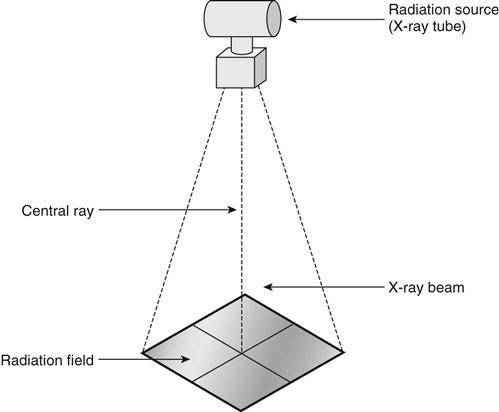
Radiography is the process of making an x-ray image called a radiograph. X-rays are produced in a vacuum tube when electrons traveling at high speed strike certain materials, such as tungsten. When the x-rays are emitted from the tube, they diverge into space, forming the cone-shaped x-ray beam. The cross section of the x-ray beam at the point of use is called the radiation field (Figure 50-1). The patient or part to be x-rayed is placed in the radiation field, between the x-ray tube and the image receptor or film.
X-rays can penetrate most substances to some degree, but some substances, such as metals and bones, are more difficult to penetrate and are said to be radiopaque. Air, gases, and soft tissues such as fat, skin, and lungs are much easier to penetrate than bone and are said to be radiolucent. During the exposure, x-rays from the tube pass through the patient. Some of the x-rays are absorbed by the patient and others are not, resulting in a pattern of varying intensity in the x-ray beam that exits on the opposite side of the patient and exposes the film. The film then has a pattern of exposure, a latent image, and must be processed to develop the latent image into one that is visible. On the finished radiograph, radiopaque objects appear light and radiolucent objects appear dark or black (Figure 50-2).
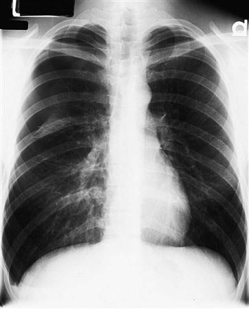
Routine plain films are simple radiographs taken of specific body structures, such as the chest or the bones of the extremities or spine. These are the examinations most often performed in ambulatory care centers and most likely to be performed by medical assistants qualified to practice radiography.
X-Ray Exposure
Prime Factors
The radiographer must take a number of factors into consideration in determining the proper technique and exposure factors for an x-ray examination. The four principal exposure factors are called the prime factors of exposure. The interaction of these factors determines the level of x-ray production and ultimately the amount of the patient’s x-ray exposure. Prime factors include the following:
The total amount of radiation in an exposure is indicated by the milliampere-seconds (mAs), which is determined by multiplying the rate of x-ray current flow (milliamperage) by the exposure time. The total amount of x-ray exposure used to perform a particular diagnostic study is a combination of kilovoltage, milliamperage, exposure time, and source-to-image distance.
Technique Charts
A technique chart located near the control console provides the radiographer with a listing of recommended milliampere-seconds, kilovoltage, and source-to-image distance settings for x-ray studies of various body parts in patients of different sizes. The radiographer must refer to technique charts before performing the ordered radiographic procedure. Some control consoles have computerized units that are preprogrammed with the required exposure settings for the selected body part and size.
Radiographic Equipment
X-Ray Tube and Housing
The x-ray tube, where the x-rays form, is surrounded by a lead-lined, protective housing (Figure 50-3). The housing absorbs any radiation that is not part of the x-ray beam. The housing protects and insulates the x-ray tube itself while providing a base for attachments that allow the radiographer to manipulate the x-ray tube and to control the size and shape of the x-ray beam.
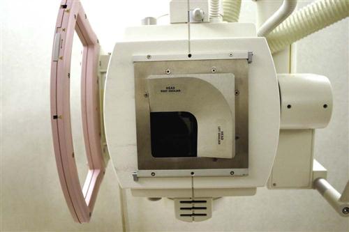
The principal attachment to the tube housing is the collimator, a boxlike device mounted beneath the opening of the housing. Collimators allow the radiographer to vary the size of the radiation field and to indicate with a light beam the size, location, and center of the field. Usually a centering light also helps align the cassette tray (Figure 50-4).
X-Ray Tube Support
The tube housing may be attached to a ceiling mount or a tube stand. Both types of mountings provide support and mobility for the heavy tube. The ceiling mount moves on a system of tracks to allow positioning of the tube at locations throughout the room. A tube stand (Figure 50-5) is a vertical support with a horizontal arm that suspends the tube over the radiographic table. The tube stand rolls along a track that is secured to the floor (and sometimes also the ceiling), allowing horizontal motion. Outpatient x-ray departments are more likely to have a tube stand.
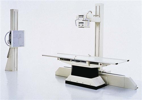
Radiographic Table
The radiographic table is a specialized unit that is more than just a support for the patient. Some tables are adjustable in height for easy patient access, and some are designed to tilt into upright and Trendelenburg positions. A floating tabletop is a feature that assists in aligning the patient to the tube and film. Using the table to move the patient allows for x-ray imaging in a variety of angles and positions.
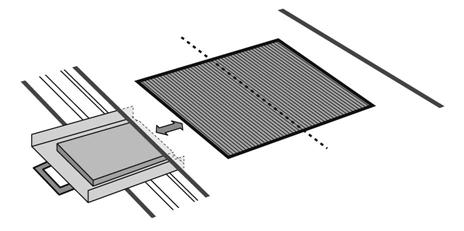
Grids and Bucky Devices
Beneath the table surface is a moving grid device called a bucky (Figure 50-6). X-ray film is placed in a cassette tray, which is then put in the bucky device under the radiographic table. This allows the cassette inside the bucky to be moved up and down the table to a point directly under the area to be x-rayed. The grid is situated between the tabletop and the film inside the cassette. It is a plate made of tissue-thin lead strips that are mounted on edge to protect the film from being fogged by scatter radiation that is displaced when the x-ray study is performed. Because the strips must be carefully aligned with the path of the x-ray beam, precise alignment of the x-ray tube in relation to the bucky is essential. When the x-ray image is actually taken, the bucky automatically moves the grid so that it is not visible on the radiograph. Bucky grids generally are used only for body parts that are more than 10 to 12 cm thick (about the size of an adult’s neck or knee). When a grid is not needed, the cassette is placed on the tabletop.
Upright Cassette Holder
The upright cassette holder, as its name implies, is a device that holds the film in an upright position for radiography. It usually is placed against a wall, and its height is adjustable. It may incorporate a bucky or stationary grid. When a grid is included, the unit may be referred to as a grid cabinet or upright bucky. When the patient is sitting or standing at the upright cassette holder for radiography, such as for a chest x-ray, the tube is angled to face the wall and cassette holder. The distance from the tube to the film may be adjusted to 40 or 72 inches, depending on the requirements of the procedure.
Control Console
The control console, located in the control booth, is the access point for the radiographer to determine exposure factors and to take the x-ray image (Figure 50-7). Radiographic control consoles have buttons, switches, dials, or digital readouts for some or all of the following functions:
• Off/On—controls the power to the control panel
• mA—allows the operator to set the milliamperage, the rate at which the x-rays are produced
• kVp—controls the kilovoltage, determining the penetrating power of the x-ray beam
• Timer—controls the duration of the exposure
• mAs—some units have an mAs control instead of mA and time settings
• Bucky—activates the motor control of the bucky device so that the grid moves during the exposure
• Meters or digital readouts—indicate the status of the settings
• Prep (ready or rotor) switch—prepares the tube for exposure
Image Receptor Systems
Cassettes and Intensifying Screens
The cassette (Figure 50-8) serves as the film holder during the x-ray procedure. It provides a light-tight, rigid structure to protect the film and also houses intensifying screens. Most cassettes have two intensifying screens, one front and one back, with the film sandwiched between them. Intensifying screens are plates coated with phosphors (fluorescent crystals) that give off light when exposed to x-rays. Their purpose is to reduce the amount of exposure required. Without intensifying screens, as much as 50 to 100 times more exposure would be needed. Intensifying screens greatly reduce the exposure of a patient to radiation during an x-ray procedure.
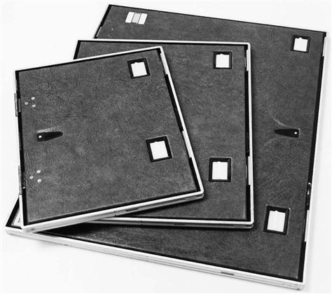
Each cassette has a small area where there is no intensifying screen and where exposure is blocked from the film by lead foil. This area is reserved for the photographic imprint of the patient identification. Its location is indicated on the front of the cassette by the position of the identifying label.
Intensifying screens are expensive and easily damaged. Damaged areas, dirt, or stains on the screens prevent light from exposing the film and result in artifacts on the image. For these reasons, it is important to avoid touching the screens and to keep the film processing area free of dust and dirt.
Film
Radiographic film is manufactured with a particular sensitivity to the light emitted by intensifying screens. Green-sensitive film is used with screens that emit green light, and blue-sensitive film is matched with blue-emitting screens. Film for routine radiography is coated on both sides so that the film responds to light from both intensifying screens. This double-emulsion system reduces the exposure required by half. Because both sides of the film are identical, a sheet of double-emulsion film does not have a “right” or “wrong” side. Film and cassettes come in standard sizes.
Film Care and Handling.
Film must be stored correctly to prevent fog, a generalized exposure that reduces image quality. A good storage area is clean, cool, and dry and is protected from radiation and processing chemical fumes. Film boxes should stand on edge with the expiration date visible. This date is checked to ensure that older film is used before its expiration date.
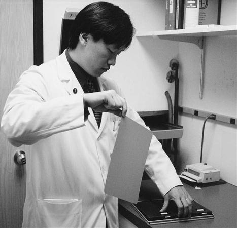
To prevent artifacts from improper film handling, be sure your hands are clean and dry and touch only the corner of the film when removing it from the cassette. Prevent bending, crimping, and scraping of the film by allowing it to hang vertically when holding it with only one hand (Figure 50-9). To place it horizontally, use both hands and hold by opposite corners.
Film Processing.
Comprehensive darkroom orientation is needed before you try to develop patients’ films. It is especially important to know how to turn on the processor properly and to recognize when it has warmed up sufficiently for correct processing.
The exposed cassette is taken to the darkroom for processing under safelight conditions. Safelights provide a red or orange light that is quite dim but provides just enough illumination for you to see where things are located. Make sure the darkroom door is locked so that no one will open it while you are processing the film.
Film identification is essential for knowing the identity of the patient represented in the image and the date and location of the examination. Serious errors in diagnosis and treatment might occur if films are not correctly identified. The identification information is typed on a card that is inserted into the photographic printer in the darkroom. The printer is used to stamp the information on the film after it has been removed from the cassette and before it is processed (Figure 50-10).
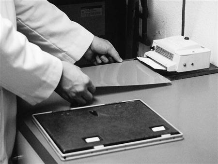
The film then is fed into the automatic processor. The cassette is reloaded with a single sheet of fresh film (Figure 50-11) from the film bin, a storage unit located under the counter. A tone or a red light on the processor indicates when it is safe to feed another film or to turn on the lights.
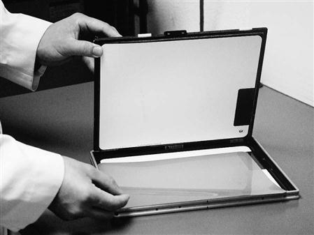
The reloaded cassette should be returned immediately to the proper place so that it is ready for use. Correct locations for cassettes are essential, because you cannot determine by looking at the cassette whether the film has been exposed. Only by following established routines and facility policies can you be confident that a cassette is unexposed and ready for use.
Daylight Processing.
Some departments have a “daylight” system for processing film without a darkroom. These systems include a special film processor and a daylight film identification camera that uses special cassettes. Films can be identified while still in the cassette, and the entire cassette then is fed into the processor. The processor automatically removes and processes the film and then reloads the cassette with fresh film.
Computed and Digital Radiography
Computed radiography (CR) is a radiographic imaging system that does not use film. An image receptor, similar to an intensifying screen, is exposed in a special cassette using conventional x-ray equipment. The radiographer inserts the exposed cassette into a special processor and selects the type of examination from a menu so that the image is processed correctly. A small beam from a high-intensity laser in the processor converts the latent image to a visible image that is converted into an electronic signal and stored in a computer. The image then can be displayed on a high-resolution monitor. Hard copies can be produced with a laser film printer.
Digital radiography is another type of filmless imaging system. Special radiographic tables and upright cabinets contain digital receptors that react to the pattern of the radiation from the patient and transmit a digital signal directly to the computer system. No cassettes and no processing are involved. Although digital radiography has been used for some time for special applications, such as fluoroscopy and angiography, technical limitations and cost factors have prevented widespread adoption of digital systems for general radiography.
Once stored in the computer system, digital images from either computed or digital radiography are organized and cataloged and can be accessed on screen from multiple locations connected to the system network. These digital images can be manipulated electronically to enhance visibility. Conventional radiographs can be added to the system by scanning them with a laser device called a film digitizer.
The computer hardware and software technology used to manage digital images in hospitals and large health care systems is called a picture archiving and communication system (PACS). These systems provide image storage, connect images with patient database information, facilitate laser printing of images, and display both images and information at workstations throughout the network as needed. PACS may include transmission equipment for teleradiology, allowing images to be viewed in remote locations, such as a physician’s home, and receiving images from remote locations, such as outlying clinics. PACS technology can transmit images directly over telephone lines and via the Internet. These advanced technologies will become more commonplace as computerized medical record systems become more widespread.
Radiographic Positioning
The medical assistant may be involved in explaining x-ray positions to a patient or in actually helping the patient into various positions, so it is important that you become familiar with commonly used terms. Terms that indicate the surfaces, directions, and planes of various body locations are based on the anatomic position.
Anatomic position (Figure 50-12) is a view of the body in which the individual is standing, facing the observer, with the palms of the hands forward. Terms that describe locations on and within the body include the following:
• Anterior: Forward or front portion of the body or body part.
• Cephalic: Pertaining to the head; toward the head.
• Caudal: Toward the tail or end of the body; away from the head; the opposite of cephalic.
• External: To the outside, at or near the surface of the body or a body part.
• Inferior: Below, farther from the head. For example, the diaphragm is inferior to the lungs.
• Internal: Deep, near the center of the body or a part; the opposite of external.
• Lateral: Referring to the side, away from the center to the left or right.
• Medial: Toward the center of the body or body part; the opposite of lateral.
• Palmar: Referring to the palm (anterior surface) of the hand.
• Plantar: Referring to the sole of the foot.
• Posterior: Backward or back portion of the body or body part; the opposite of anterior.

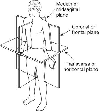
Besides anatomic positional terms, procedures for radiographic positioning also are described using the planes of the body (Figure 50-13). The sagittal plane divides the body into right and left parts, and the midsagittal plane divides the body into equal right and left parts. The coronal plane (sometimes called the frontal plane) divides the body into anterior and posterior parts. The midcoronal or midfrontal plane divides the body into relatively equal parts; it passes through the external auditory meatus (the opening of the ear), the center of the shoulder, the greater trochanter (the bony prominence in the lateral hip area), and the lateral malleolus (the bony prominence on the lateral surface of the ankle). The transverse plane divides the body into superior and inferior portions. It may be drawn at any level.
The medical assistant may assist with radiographic procedures by helping position the patient for a particular x-ray view. These positions can be used as follows in x-ray positioning:
• Dorsal recumbent: Lying on the back (supine) with the knees bent and the feet flat on the table
• Lateral recumbent: Lying on the side
• Ventral recumbent: Lying face down, prone
• Supine: Lying on the back face up
Projections
A radiographic projection indicates the relative positions of the body part to be x-rayed, the film, and the placement of the x-ray tube.
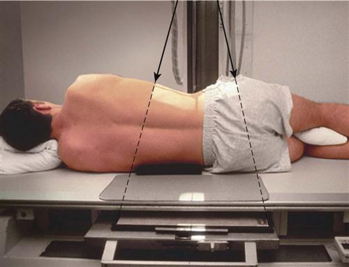
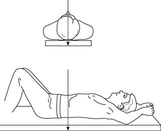
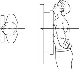
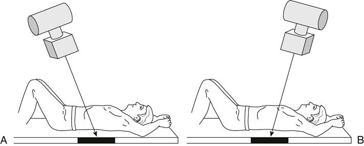
For a frontal projection, the coronal plane of the body or body part is parallel to the film plane and the central ray is perpendicular to both. If the patient is supine, or facing the x-ray tube, the projection is said to be anteroposterior (AP) (Figure 50-14). If the patient is prone, or facing the film, the projection is said to be posteroanterior (PA) (Figure 50-15). Note that these terms indicate the direction of the x-ray beam, from front to back or back to front.
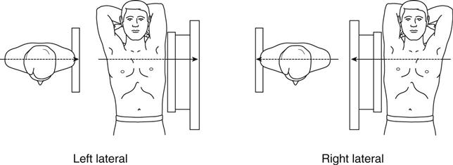
Lateral projections are those in which the sagittal plane of the body or body part is parallel to the film. Lateral projections are always named for the side of the patient that is nearest the film; that is, either left or right lateral (Figure 50-16).
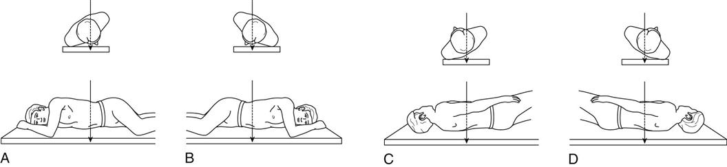
Oblique projections are those in which the body or part is rotated so that the projection is neither frontal nor lateral. Oblique projections also are named for the part of the body nearest the film. For example, in a right anterior oblique (RAO) projection, the patient’s right, anterior aspect is closest to the film. Figure 50-17 illustrates all four oblique projections: RAO, right posterior oblique (RPO), left anterior oblique (LAO), and left posterior oblique (LPO).
Axial projections, sometimes referred to as semiaxial projections, are radiographs taken with a longitudinal angulation of the x-ray beam. The x-ray beam is projected at an angle, either cephalad (toward the head) or caudad (away from the head) (Figure 50-18).
Diagnostic Imaging Modalities
Fluoroscopy and Contrast Media
Fluoroscopy
Fluoroscopy is a technique in which special equipment is used to allow the radiologist to view x-ray images in motion. Fluoroscopy also allows the physician to survey an area quickly, without the delay involved in taking and processing films. Most fluoroscopic units are properly called radiographic/fluoroscopic (R/F) units, because they are designed to take both x-ray images and fluoroscopic views. The x-ray films taken during a fluoroscopic procedure, which are called spot films, record the image as seen on the fluoroscope; sometimes the entire fluoroscopic examination is recorded digitally. After the fluoroscopic portion of the study is complete, larger radiographs usually are taken for comprehensive visualization of the entire anatomic region.
An example of a fluoroscopic diagnostic procedure is a barium swallow. If the physician suspects that the patient has difficulty swallowing, a fluoroscope is used to visualize the actual movement of the substance down the esophagus and into the stomach while the patient is in the act of swallowing. Fluoroscopic procedures typically require the use of a contrast medium, such as barium.
X-Ray Studies Using Contrast Media
Although the lungs and bony structures of the body produce clear x-ray images on plain film radiographs, internal organs, such as the stomach and the kidneys, are difficult to see because they absorb radiation to the same degree as the tissues that surround them. To enhance visibility of these structures, special agents, called contrast media, can be used to fill hollow organs and demonstrate their inner contours. Although gases such as air and carbon dioxide sometimes are used as contrast media, the use of radiopaque substances, such as barium sulfate or iodine compounds, is far more common. The agent and the technique vary with the structures to be viewed (Table 50-1).
TABLE 50-1
Radiographic Procedures Using Contrast Media
| EXAMINATION | CONTRAST MEDIUM | ROUTE OF ADMINISTRATION | STRUCTURES SHOWN |
| Angiocardiography | Iodine compounds | Intra-arterial injection via femoral or brachial catheter | Heart and large vessels |
| Angiography | Iodine compounds | Intra-arterial or intravenous injection | Blood vessels |
| Arteriography | Iodine compounds | Intra-arterial injection via catheter | Arteries |
| Arthrography | Iodine compounds | Direct injection into joint capsule | Joints, especially knee, shoulder, and ankle |
| Barium swallow | Barium sulfate suspension | Oral | Esophagus |
| Hysterosalpingography | Iodine compounds | Direct injection via cannula | Uterus and fallopian tubes |
| Intravenous urography | Iodine compounds | Intravenous injection | Kidneys, ureters, and urinary bladder |
| Lower gastrointestinal (GI) series (barium enema) | Barium sulfate suspension, sometimes also with air | Rectal catheter | Colon |
| Lymphangiography | Iodine compounds | Direct injection into lymphatic vessels in the feet | Lymphatic vessels and lymph nodes |
| Myelography | Iodine compounds | Intrathecal injection (spinal tap) | Spinal canal |
| Upper GI series | Barium sulfate suspension | Oral | Esophagus, stomach, and duodenum |
Stay updated, free articles. Join our Telegram channel

Full access? Get Clinical Tree


