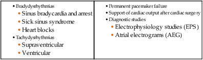
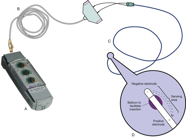
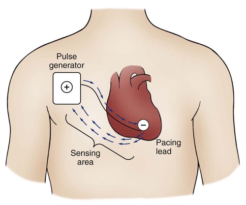
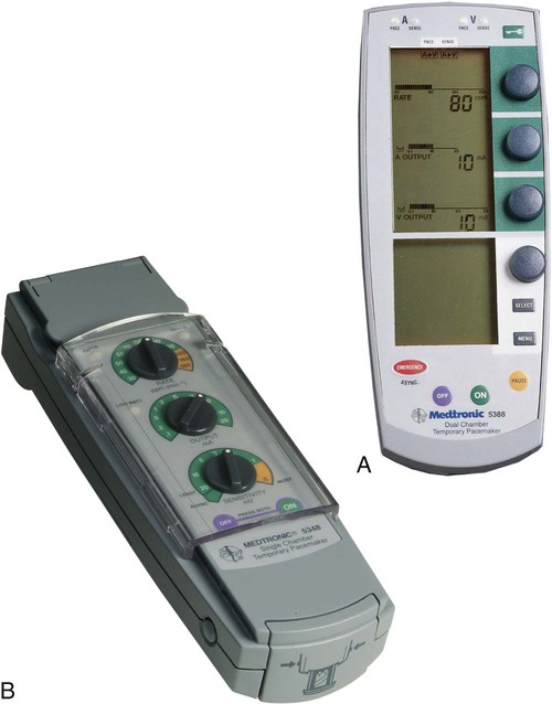
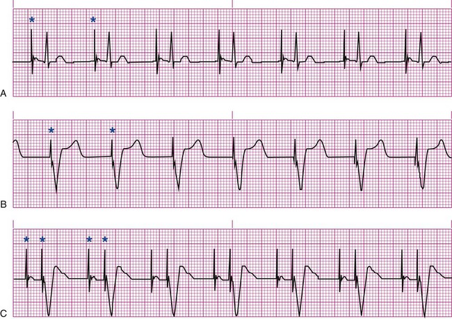
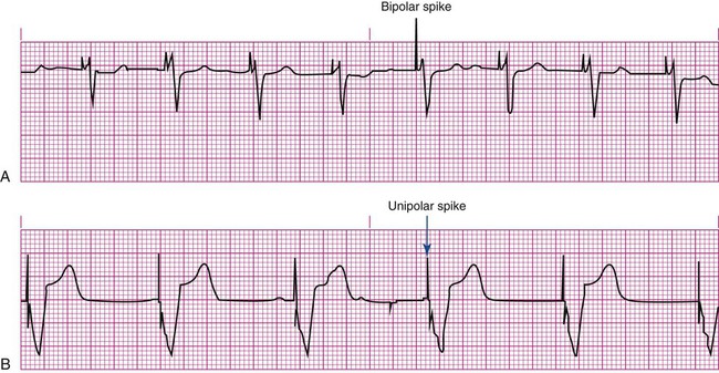
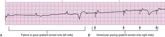
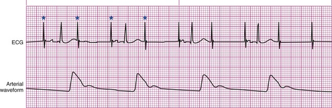
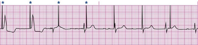
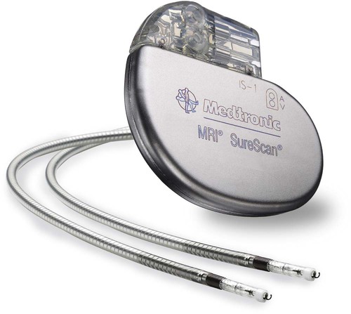
Pacemakers are electronic devices that can be used to initiate the heartbeat when the heart’s intrinsic electrical system cannot effectively generate a rate adequate to support cardiac output. Pacemakers may be used temporarily, either supportively or prophylactically, until the condition responsible for the rate or conduction disturbance resolves. They also may be used on a permanent basis if the patient’s condition persists despite adequate therapy. The use of permanent pacemakers as a form of device-based therapy has expanded significantly in the last decade.1 The clinical indications for instituting temporary pacemaker therapy are similar regardless of the cause of the rhythm disturbance that necessitates the placement of a pacemaker (Box 16-1). The causes range from ischemia and electrolyte imbalances to sequelae related to acute myocardial infarction (MI) or cardiac surgery. Several diagnostic uses for temporary pacing have evolved. Electrophysiology studies (EPS) are performed in cardiac catheterization laboratories equipped with specialized pacing equipment. During an EPS, catheters with pacing electrodes are used to diagnose the patient’s potential for dysrhythmias.2 These electrodes are used to induce dysrhythmias in patients with recurrent symptomatic tachydysrhythmias. This allows the physician to closely evaluate the particular dysrhythmia and determine appropriate therapy. For those patients whose tachydysrhythmia is found to be refractory to conventional antidysrhythmic therapy, radiofrequency (RF) current catheter ablation of the responsible tissue can be done safely and effectively in the electrophysiology laboratory. After a mapping procedure has localized the site of dysrhythmia formation, short bursts of RF current are delivered through the catheter, destroying the offending tissue with heat. Ablation has been shown to be an effective treatment for patients with symptomatic supraventricular tachycardias that result from atrioventricular (AV) node re-entry or accessory pathways, such as Wolff-Parkinson-White syndrome.3,4 Catheter ablation may also be used as a therapeutic strategy for selected patients with atrial fibrillation.5 Intracardiac electrograms—recordings of cardiac electrical activity obtained from pacing electrodes—may provide useful diagnostic information. The atrial electrogram (AEG) is an amplified recording of atrial activity that can be obtained through the use of an atrial pacing electrode or an esophageal pill electrode and a standard electrocardiogram (ECG) machine. It may be used after cardiac surgery to facilitate the diagnosis of supraventricular dysrhythmias in patients with temporary atrial epicardial wires already in place.6 The bipolar lead used in transvenous pacing has two electrodes on one catheter (Fig. 16-1). The distal, or negative, electrode is at the tip of the pacing lead and is in direct contact with the heart, usually inside the right atrium or ventricle. Approximately 1 cm from the negative electrode is a positive electrode. The negative electrode is attached to the negative terminal, and the positive electrode is attached to the positive terminal of the pulse generator, either directly or by means of a bridging cable (see Fig. 16-1B). A unipolar pacing system (epicardial or transvenous) has only one electrode (the negative electrode) making contact with the heart. For a permanent pacemaker, the positive electrode can be created by the metallic casing of the subcutaneously implanted pulse generator (Fig. 16-2), or as is the case with a unipolar epicardial lead system, the positive electrode can be formed by a piece of surgical steel wire sewn into the subcutaneous tissue of the chest or the metal portion of a surface ECG electrode. Because the unipolar pacing system has a wide sensing area as a result of the relatively long distance between the negative and positive electrodes, it has better sensing capabilities than does a bipolar system. However, this feature makes the unipolar system more susceptible to sensing extraneous signals, such as the electrical artifacts created by normal muscle movements (i.e., myopotentials) or by external electromagnetic interference (EMI), which may result in inappropriate inhibition of the pacing stimulus. This problem is of more concern in permanent pacing systems, in which the “can” of the pacemaker generator may be used as a part of the pacing circuit. Because the can is located near a large muscle mass, upper body movement can result in the inappropriate sensing of myopotentials.7 Several routes are available for temporary cardiac pacing (Box 16-2). Permanent pacing usually is accomplished transvenously, although when a thoracotomy is otherwise indicated, as in cardiac surgery, the physician may elect to insert permanent epicardial pacing wires. Transcutaneous cardiac pacing involves the use of two large skin electrodes, one placed anteriorly and the other posteriorly on the chest, connected to an external pulse generator. It is a rapid, noninvasive procedure that nurses can perform in the emergency setting and is recommended in the advanced cardiac life support (ACLS) algorithm for the treatment of symptomatic bradycardia that does not respond to atropine.8 Improved technology related to stimulus delivery and the development of large electrode pads that help disperse the energy have helped reduce the pain associated with cutaneous nerve and muscle stimulation. Discomfort may still be an issue for some patients, particularly when higher energy levels are required to achieve capture. This route is typically used as a short-term therapy until the situation resolves or another route of pacing can be established. The insertion of temporary epicardial pacing wires has become a routine procedure during most cardiac surgical cases. Ventricular and, in many cases, atrial pacing wires are loosely sewn to the epicardium. The terminal pins of these wires are pulled through the skin before the chest is closed. If both chambers have pacing wires attached, the atrial wires exit subcostally to the right of the sternum and the ventricular wires exit in the same region but to the left of the sternum. These wires can be removed several days after surgery by gentle traction at the skin surface with minimal risk of bleeding.9 In the 1960s, pacemaker terminology was limited to fixed-rate and demand pacing; AV sequential pacing was introduced in the early 1970s. Although these terms are still useful for understanding pacemaker function (Box 16-3), the continued expansion of functional capabilities of pulse generators has made it necessary to develop a more precise classification system. In 1974, the Inter-Society Commission for Heart Disease (ICHD) adopted a three-letter code for describing the various pacing modalities available. The code has since undergone several revisions, including the addition of two more letters representing programming characteristics and multisite pacing functions, to accommodate the development of newer devices that are rate responsive or that pace from more than one site within the atria and the ventricles. Table 16-1 describes the current five-letter code.10 The original three-letter code remains adequate to describe temporary pacemaker function. TABLE 16-1 Modified from Bernstein AD, et al. The Revised NASPE/BPEG generic pacemaker code for antibradycardia, adaptive-rate and multisite pacing. PACE. 2002;25:260. The original code is based on three categories, each represented by a letter. The first letter refers to the cardiac chamber that is paced. The second letter designates which chamber is sensed, and the third letter indicates the pacemaker’s response to the sensed event. These three letters are used to describe the mode of pacing. For example, a VVI pacemaker paces the ventricle when the pacemaker fails to sense an intrinsic ventricular depolarization, but sensing of a spontaneous ventricular depolarization inhibits ventricular pacing. A VOO pacemaker paces the ventricle at a fixed rate and has no sensing capabilities. In DDD pacing, atrial and ventricular leads are used for pacing and sensing. In response to sensed activity, the pacemaker inhibits the pacing stimulus; a sensed P wave in the atrium inhibits the atrial spike, and a sensed R wave in the ventricle inhibits the ventricular pacing spike. A sensed P wave may also be used to trigger a ventricular pacing stimulus if normal conduction through the AV node is impaired. Table 16-2 provides a description of temporary pacing modes. TABLE 16-2 EXAMPLES OF TEMPORARY PACING MODES Physiologic pacing has traditionally been used to describe modes in which the normal physiologic, or sequential, relationship between atrial and ventricular stimulation and contraction is maintained. AV synchrony increases the volume in the ventricle before contraction and helps to improve cardiac output. This may be achieved with atrial pacing in patients who have an intact conduction system or by dual chamber pacing when atrial-to-ventricular conduction is impaired (i.e., during heart block). More recently, physiologic pacing has evolved to include the maintenance of ventricular synchrony as well. Strategies to achieve this include minimizing the use of ventricular pacing and simultaneous pacing of both right and left ventricles.1 The rate control (Fig. 16-3) regulates the number of impulses that can be delivered to the heart per minute. The rate setting depends on the physiologic needs of the patient, but it usually is maintained between 60 and 80 beats/min. Pacing rates for overdrive suppression of tachydysrhythmias may greatly exceed these values. Some generators have special controls for overdrive pacing that allow for rates of up to 800 stimuli per minute. If the pacemaker is operating in a dual-chamber mode, the ventricular rate control also regulates the atrial rate. The output dial regulates the amount of electrical current, measured in milliamperes (mA), that is delivered to the heart to initiate depolarization. The point at which depolarization occurs, called threshold, is indicated by a myocardial response to the pacing stimulus (i.e., capture). Threshold can be determined by gradually decreasing the output setting until 1 : 1 capture is lost. The output setting is then slowly increased until 1 : 1 capture is re-established; this threshold to pace is less than 1 mA with a properly positioned pacing electrode. The output is set two to three times higher than threshold, because thresholds tend to fluctuate over time. Box 16-4 details the procedure for measuring pacing thresholds. Separate output controls for atrium and ventricle are used with a dual-chamber pulse generator. The sensitivity control regulates the ability of the pacemaker to detect the heart’s intrinsic electrical activity. Sensitivity is measured in millivolts (mV) and determines the size of the intracardiac signal that the generator will recognize. If the sensitivity is adjusted to its most sensitive setting—a setting of 0.5 to 1 mV—the pacemaker can respond even to low-amplitude electrical signals coming from the heart. Turning the sensitivity to its least sensitive setting (i.e., adjusting the dial to a setting of 20 mV or to the area labeled async) results in inability of the pacemaker to sense any intrinsic electrical activity and causes the pacemaker to function at a fixed rate. A sense indicator (often a light) on the pulse generator signals each time intrinsic cardiac electrical activity is sensed. A pulse generator may be designed to sense atrial activity or ventricular activity, or both. Box 16-5 describes the procedure for measuring sensitivity. The sensitivity is set at half of the value of the sensitivity threshold to ensure that all appropriate intrinsic cardiac signals are sensed. For example, if the measured sensitivity threshold is 3.0 mV, the generator is set at 1.5 mV. The pacemaker’s sensing ability can be quickly evaluated by observing for a change in pacing rhythm in response to spontaneous depolarizations. Temporary dual chamber pacemakers have other settings that are required in the DDD mode (see Fig. 16-3B). The lower rate, or base rate, determines the rate at which the generator will pace when intrinsic activity falls below the set rate of the pacemaker. The upper rate determines the fastest ventricular rate the pacemaker will deliver in response to sensed atrial activity. This setting is needed to protect the patient’s heart from being paced in response to rapid atrial dysrhythmias. The pulse width, which can be adjusted from 0.05 to 2 msec, controls the length of time that the pacing stimulus is delivered to the heart. There also is an atrial refractory period, programmable from 150 to 500 msec, which regulates the length of time, after a sensed or paced ventricular event, during which the pacemaker cannot respond to another atrial stimulus. An emergency button is also available on most models to allow for rapid initiation of asynchronous (DOO) pacing during an emergency. All patients with temporary pacemakers require continuous ECG monitoring. The pacing artifact is the spike that is seen on the ECG tracing as the pacing stimulus is delivered to the heart. A P wave is visible after the pacing artifact if the atrium is being paced (Fig. 16-4A). Similarly, a QRS complex follows a ventricular pacing artifact (see Fig. 16-4B). With dual-chamber pacing, a pacing artifact precedes both the P wave and the QRS complex (see Fig. 16-4C). Not all paced beats look alike. For example, the artifact (spike) produced by a unipolar pacing electrode is larger than that produced by a bipolar lead (Fig. 16-5). The QRS complex of paced beats appears different, depending on the location of the pacing electrode. If the pacing electrode is positioned in the RV, a left bundle branch block (LBBB) pattern is displayed on the ECG. A right bundle branch block (RBBB) pattern is visible if the pacing stimulus originates from the left ventricle (LV). Failure of the pacemaker to deliver the pacing stimulus results in disappearance of the pacing artifact, even if the patient’s intrinsic rate is less than the set rate on the pacer (Fig. 16-6). This can occur intermittently or continuously and can be attributed to failure of the pulse generator or its battery, a loose connection between the various components of the pacemaker system, broken lead wires, or stimulus inhibition as a result of EMI. Tightening connections, replacing the batteries or the pulse generator itself, or removing the source of EMI may restore pacemaker function. If the pacing stimulus fires but fails to initiate a myocardial depolarization, a pacing artifact will be present but will not be followed by the expected P wave or QRS complex, depending on the chamber being paced (Fig. 16-7). This loss of capture most often can be attributed to displacement of the pacing electrode or to an increase in threshold (electrical stimulus necessary to elicit a myocardial depolarization) as a result of medications, metabolic disorders, electrolyte imbalances, or fibrosis or myocardial ischemia at the site of electrode placement. In many cases, increasing the output (mA) elicits capture. For transvenous leads, repositioning the patient onto the left side may improve lead contact and restore capture. Pacing can occur at inappropriate rates. For example, impending battery failure in a permanent pacemaker can result in a gradual decrease in the paced rate, also referred to as rate drift. Inappropriate stimuli from a pacemaker may result in a pacemaker-mediated tachycardia. This usually is caused by sensing of inappropriate signals in a dual-chamber pacemaker that is in a trigger mode, such as DDD. The tachycardia can be terminated by placing a magnet over the generator to transiently suspend sensing.11 Sensing abnormalities include both undersensing and oversensing. Undersensing is the inability of the pacemaker to sense spontaneous myocardial depolarizations. Undersensing results in competition between paced complexes and the heart’s intrinsic rhythm. This malfunction is manifested on the ECG by pacing artifacts that occur after or are unrelated to spontaneous complexes (Fig. 16-8). Undersensing can result in the delivery of pacing stimuli into a relative refractory period of the cardiac depolarization cycle (see Fig. 12-25 in Chapter 12). A ventricular pacing stimulus delivered into the downslope of the T wave (R-on-T phenomenon) is a real danger with this type of pacer aberration, because it may precipitate a lethal dysrhythmia. The nurse must act quickly to determine the cause and initiate appropriate interventions. Often, the cause can be attributed to inadequate wave amplitude (height of the P or R wave). If this is the case, the situation can be promptly remedied by increasing the sensitivity by moving the sensitivity dial toward its lowest setting. Other possible causes include inappropriate (asynchronous) mode selection, lead displacement or fracture, loose cable connections, and pulse generator failure. It is important to be aware of all sources of EMI within the critical care environment that may interfere with the pacemaker’s function. Sources of EMI in the clinical area include electrocautery, defibrillation current, radiation therapy, magnetic resonance imaging devices, and transcutaneous electrical nerve stimulation (TENS) units.12 In most cases, if EMI is suspected of precipitating pacemaker malfunction, conversion to the asynchronous mode (fixed rate) can maintain pacing until the cause of the EMI is removed. Because the pacing electrode provides a direct, low-resistance path to the heart, the nurse takes special care while handling the external components of the pacing system to avoid conducting stray electrical current from other equipment. Even a small amount of stray current transmitted through the pacing lead could precipitate a lethal dysrhythmia. The possibility of microshock can be minimized by wearing gloves when handling the pacing wires and by proper insulation of terminal pins of pacing wires when they are not in use (Box 16-6). The latter precaution can be accomplished by the use of caps provided by the manufacturer or by improvising with a plastic syringe or section of disposable rubber glove. The wires are taped securely to the patient’s chest to prevent accidental electrode displacement. Prevention of Microshock • Wear gloves when handling pacing wires • Secure all connections between pulse generator, pacing cable, and leads • Insulate lead tips with nonconducting materials when not attached to generator (manufacturer’s cap, finger cot, plastic syringe) • Keep dressings and pacing equipment dry • Make sure all electrical equipment is properly grounded Patient teaching for the person with a temporary pacemaker emphasizes the prevention of complications (Box 16-7). The patient is instructed not to handle any exposed portion of the lead wire and to notify the nurse if the dressing over the insertion site becomes soiled, wet, or dislodged. The patient also is advised not to use any electrical devices brought in from home that could interfere with pacemaker functioning. Patients with temporary transvenous pacemakers need to be taught to restrict movement of the affected extremity to prevent lead displacement. Almost 400,000 permanent pacemakers are implanted annually in the United States, and critical care nurses are likely to encounter these devices in their clinical practice.13 These pacemakers were originally designed to provide an adequate ventricular rate in patients with symptomatic bradycardia. Today, the goal of pacemaker therapy is to simulate, as much as possible, normal physiologic cardiac depolarization and conduction. Sophisticated generators permit rate-responsive pacing, effecting responses to sensed atrial activity (DDD) or to a variety of physiologic sensors (body motion or minute ventilation). For patients who do not have a functional sinus node that can increase their heart rate, rate-responsive pacemakers may improve exercise capacity and quality of life.14 Table 16-3 describes the types of rate-responsive pacing generators in clinical use. The concept of physiologic pacing continues to evolve, because studies have indicated that pacing initiated from the RV apex—even in a dual-chamber mode—may promote heart failure in patients with permanent pacemakers.1 This has prompted further research to identify alternative sites for pacing and modes that can maximize intrinsic AV conduction and minimize ventricular pacing.15 TABLE 16-3 PERMANENT PACEMAKER RATE-RESPONSE PACING MODES The patient who undergoes implantation of a permanent pacemaker is usually in the hospital for less than 24 hours. Longer lengths of stay are expected for patients with serious complications such as MI or cardiogenic shock. Technologic advances in the computer industry have had a major impact on permanent pacemakers. Microprocessors have allowed for the development of increasingly smaller generators despite the incorporation of more complex features. Today’s generators are smaller, more energy-efficient, and more reliable than previous models. The most recent enhancement has been the release of a pacemaker that is compatible with magnetic resonance imaging (MRI).16 An example of a modern pacemaker is shown in Figure 16-9. A rapidly expanding role for permanent pacemakers has been the use of these devices as a type of nonpharmacologic therapy for treatment of conditions such as heart failure and atrial fibrillation.
Cardiovascular Therapeutic Management
Pacemakers
Indications for Temporary Pacing
Diagnostic Indications
The Pacemaker System
Pacing Lead Systems
Pacing Routes
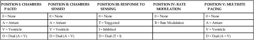
Five-Letter Pacemaker Codes
POSITION I: CHAMBERS PACED
POSITION II: CHAMBERS SENSED
POSITION III: RESPONSE TO SENSING
POSITION IV: RATE MODULATION
POSITION V: MULTISITE PACING
0 = None
0 = None
0 = None
0 = None
0 = None
A = Atrium
A = Atrium
T = Triggered
R = Rate Modulation
A = Atrium
V = Ventricle
V = Ventricle
I = Inhibited
V = Ventricle
D = Dual (A + V)
D = Dual (A + V)
D = Dual (T + I)
D = Dual (A + V)
PACING MODE
DESCRIPTION
Asynchronous
AOO
Atrial pacing, no sensing
VOO
Ventricular pacing, no sensing
DOO
Atrial and ventricular pacing, no sensing
Synchronous
AAI
Atrial pacing, atrial sensing, inhibited response to sensed P waves
VVI
Ventricular pacing, ventricular sensing, inhibited response to sensed QRS complexes
DVI
Atrial and ventricular pacing, ventricular sensing; both atrial and ventricular pacing are inhibited if a spontaneous ventricular depolarization is sensed
DDD
Both chambers are paced and sensed; inhibited response of the pacing stimuli to sensed events in their respective chambers; triggered response to sensed atrial activity to allow for rate-responsive ventricular pacing
Pacemaker Settings
Pacing Artifacts
Pacemaker Malfunctions
Pacing Abnormalities
Sensing Abnormalities
Undersensing.
Nursing Management
Prevention of Pacemaker Malfunction
Microshock Protection
 Box 16-6 Patient Safety Alert

Patient Education
Permanent Pacemakers
PULSE GENERATOR
DESCRIPTION
AAIR
AAI features plus rate-responsive pacing; used for patients with a symptomatic bradycardia who have a paceable atrium and intact atrioventricular conduction
VVIR
VVI features plus rate-responsive pacing; used for patients with an atrium that is unpaceable as a result of chronic atrial fibrillation or other atrial dysrhythmia
DDDR
DDD features plus rate-responsive pacing; used for patients with a symptomatic bradycardia in which the atrium is paceable but atrioventricular conduction is, or may become, unreliable
![]()
Stay updated, free articles. Join our Telegram channel

Full access? Get Clinical Tree


Cardiovascular Therapeutic Management
Get Clinical Tree app for offline access
