Section Fourteen Invasive Hemodynamic Monitoring
PROCEDURE 87 Central Venous Pressure Measurement
PROCEDURE 88 Arterial Line Insertion and Monitoring
PROCEDURE 87 Central Venous Pressure Measurement
Central venous pressure is also known as CVP or right atrial pressure (RAP).
INDICATIONS
1. To monitor volume status and right ventricular function. CVP monitoring is most helpful in patients without preexisting cardiopulmonary disease (Mickiewicz, Dronen, & Younger, 2004).
2. To guide the administration of fluids, diuretics, and vasoactive drugs when other invasive monitoring options are not available. CVP is a key monitoring parameter used to guide resuscitation as part of early goal-directed therapy (EGDT) for severe sepsis (Dellinger et al., 2004).
3. To assist in the diagnosis of cardiac tamponade (Mickiewicz et al., 2004).
CONTRAINDICATIONS AND CAUTIONS
1. Increases in CVP may occur as a result of increased cardiac output, right ventricular infarct or failure, increased vascular volume, cardiac tamponade, tension pneumothorax, constrictive pericarditis, or pulmonary hypertension. Falsely elevated CVP measurements may occur in the setting of a pneumothorax, positive-pressure ventilation, or chronic obstructive pulmonary disease.
2. Inaccurate readings can be caused by dislocation of the tip of the central line from the superior vena cava or improper manometer or transducer positioning. Zero the transducer whenever the patient’s position is changed.
3. Decreases in CVP may be due to any condition that decreases preload such as hypovolemia, drug-induced vasodilation, or shock of any etiology.
EQUIPMENT
Transducer
Cardiac monitor with hemodynamic monitoring capability
Pressure tubing with continuous flush device and transducer
Pressure extension tubing (extra length of pressure tubing if planning to mount transducer on IV pole)
Two or three three-way stopcocks
250- or 500-ml bag of flush solution per institutional policy (normal saline or heparin solution)
PATIENT PREPARATION
1. See Procedures 62 through 65 for information about central line insertion. Preexisting central venous lines or ports, without a valve (i.e., Groshong), may be used for initial evaluation of CVP until another central line is inserted (Gilboy & Tanabe, 2006).
2. Place the patient in the supine position with the head of the bed flat or elevated no more than 30 degrees.
3. Locate and mark the phlebostatic axis with the skin marker to ensure that the same zero reference point is used for consistent measurements. The phlebostatic axis is found by locating the junction of the fourth intercostal space and the midaxillary line (Figure 87-1).

PROCEDURAL STEPS
Manometer
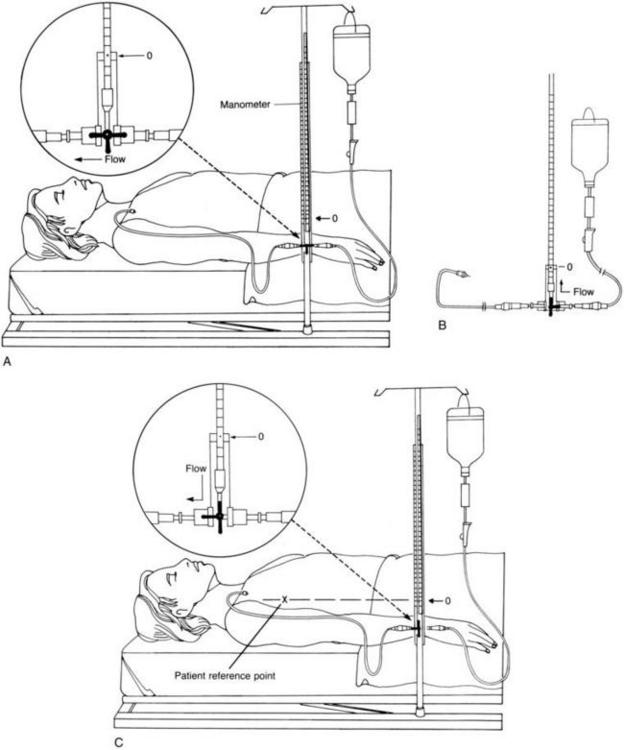
1. Turn the stopcock off to the manometer and flush the tubing with IV fluid (Figure 87-2, A).
2. Attach the manometer tubing to the central venous line and flush to ensure patency.
3. Position the zero mark on the water manometer (not the base of the manometer) at the phlebostatic angle. The manometer can be either secured to an IV pole or hand held at the point of reference.
4. Turn the stopcock off to the patient and open it between the IV solution and the manometer. Allow the manometer to fill slowly with IV fluid up to the 25-cm level. Note that the faster the IV fluid is running, the faster the manometer fills. Avoid letting the fluid run out the top of the manometer, because contamination of the manometer may result (Figure 87-2, B).
5. Turn the stopcock off to the IV fluid and open between the patient and manometer. This causes the fluid level to fall and fluctuate with respirations (Figure 87-2, C).
6. Take the CVP reading when the fluid level stabilizes. The reading should be taken from the base of the meniscus at the end of expiration. If the patient is spontaneously breathing, the fluid in the manometer slightly drops with inspiration; end-expiration is seen when the fluid in the manometer rises. In a ventilated patient, the fluid height in the manometer increases during inspiration and drops at end-expiration.
7. Turn the stopcock off to the manometer and run the IV fluids through the central venous line as prescribed
8. Document the reading and the patient’s position.
9. Normal CVP ranges from 6 to 12 cm H2O (Mickiewicz et al., 2004). When monitoring CVP, the trend is more significant than a single reading.
Transducer
1. Assemble the pressure tubing and transducer and zero the transducer as described in Procedure 88: Arterial Line Insertion and Monitoring. The transducer setup will convert the pressure in the right atrium to an electrical signal that can be viewed on the monitor.
2. The transducer can be patient- or pole-mounted. In order to obtain accurate measurements, the transducer must also be placed at the level of the phlebostatic axis and zeroed.
3. Observe the CVP values and waveform. If the patient is spontaneously breathing, note the pressure at the end of inspiration. In a ventilated patient, note the pressure at the end of expiration.
4. Document the reading and the patient’s position.
5. Normal CVP ranges from 6 to 12 cm H2O (1 mm Hg equals 1.3595 cm H2O) (Mickiewicz et al., 2004). When monitoring CVP, the trend is more significant than a single reading.
AGE-SPECIFIC CONSIDERATIONS (Nichols et al., 2006)
1. CVP catheters are indicated for children with large blood loss or with fluid shifts or those requiring vasoactive drugs. They may be placed in the internal jugular, subclavian, or femoral vein.
2. Normal CVP values in infants are difficult to define. Healthy infants usually have values between –2 and 4 mm Hg. Infants and children with congenital heart or respiratory diseases will have readings between 2 and 6 mm Hg. Elevated pressures may indicate cardiac dysfunction, increased intrathoracic pressure, or volume overload. Note that the normal values listed above for adults are in cm H2O, not mm Hg; 1 mm Hg equals 1.3595 cm H2O.
3. Because veins are small in infants and children, cannulation may be difficult and arterial puncture is a risk.
4. Proper positioning and zeroing of the transducer are especially important in children because minute changes can be a significant finding.
COMPLICATIONS
1. As with other procedures using central venous catheters, complications may include infection, phlebitis, venous thrombosis, and air embolism.
2. Occlusion of the catheter caused by improper positioning of the stopcock results in slowing or cessation of IV fluid administration through the central venous line.
3. Hemorrhage may result from disconnection of the tubing from the central venous catheter.
4. Inaccurate readings may result from air bubbles in the circuit, a transducer that is not correctly calibrated (zeroed), malposition of the catheter tip, increased intrathoracic pressure (positive pressure ventilation, coughing, tension pneumothorax, or Valsalva maneuver), occlusions of catheter or tubing, inaccurate reference point, readings at the wrong phase of respiration, or readings by different observers (Mickiewicz et al., 2004).
Blot F., Laplance A. Accuracy of totally implantable ports, tunneled, single- and multi-lumen central venous catheters for measurement of central venous pressure. Intensive Care Medicine. 2000;26:1837–1842.
Dellinger R.P., Carlet J.M., Masur H., Gerlach H., Calandra T., Cohen J., et al. Surviving sepsis campaign. Critical Care Medicine. 2004;32:858–873.
Gilboy N., Tanabe P. Can different types of central venous catheters be used to obtain central venous pressures in an emergent situation? Advanced Emergency Nursing Journal. 2006;28:269–274.
Mickiewicz M., Dronen S.C., Younger J.G. Central venous catheterization and central venous pressure monitoring. In: Roberts J.R., Hedges J.R. Clinical procedures in emergency medicine. 4th ed. Philadelphia: Saunders; 2004:413–446.
Nichols D.G., Ungerleider R.M., Spevak P.J., Greely W.J., Cameron D.E., Lappe D.G., Wetzel R.C. Critical heart disease in infants and children, 2nd ed. St Louis: Mosby, 2006.
PROCEDURE 88 Arterial Line Insertion and Monitoring
An arterial line is also known as an A-line or an art line.
INDICATIONS
1. To monitor arterial pressure accurately and continuously in patients who are, or who have the potential to become, hemodynamically unstable.
2. To monitor the response to vasoactive drugs.
3. To facilitate frequent sampling of arterial blood gases (ABGs) and other laboratory specimens.
4. To determine derived hemodynamic parameters, such as the mean arterial pressure (MAP). This is helpful for calculating and monitoring cerebral perfusion pressure.
CONTRAINDICATIONS AND CAUTIONS
1. Knowledge and understanding of the arterial line monitoring system, the waveforms, and how to obtain accurate values is necessary when assisting with insertion and monitoring of the A-line.
2. Significant blood loss may occur if the tubing is disconnected.
3. Close patient monitoring is necessary for any patient with an A-line in place, and monitoring alarms should always be enabled to alert the nurse of hemodynamic changes or system malfunction.
4. Avoid A-line insertion in extremities with injuries that may compromise distal circulation.
EQUIPMENT
Arterial catheter or 18- to 20-G, 1- to 2-in intravenous (IV) catheter
Lidocaine 1% (without epinephrine) for local anesthesia
18-G, 1½-in needle (to draw up lidocaine)
25-G, ½-in needle (to administer lidocaine)
250- to 500-ml bag of flush solution, normal saline or heparinized saline, per institutional policy
Cardiac monitor with invasive monitoring capability
Recorder (preferably analog recorder)
†Microdrip IV tubing
†Pressure tubing with continuous flush device
†Pressure transducer (if not already part of the pressure tubing setup)
†Pressure extension tubing
†Long pressure extension tubing (for pole-mounted transducer)
†Two or three (three-way) stopcocks (number used depends on how blood draws are performed, i.e., one- or two-stopcock method)
†Dead-ender nonvented caps for stopcock ports
Pole-mounted transducer holder (optional)
Dressing supplies per institutional protocol, e.g., tincture of benzoin, adhesive tape or surgical tape closures, and transparent occlusive dressing
Blood drawing supplies: ABG syringe, blood tubes as needed, vacutainer holder with Luer adaptor, and one or two 10-ml syringes (supplies needed depend on laboratory studies ordered and blood draw technique (see steps 12a and 12b). (Indicates equipment that may come prepackaged in a pressure tubing and transducer set)
PATIENT PREPARATION
1. Establish cardiac monitoring (see Procedure 55).
2. Check with the physician regarding the site to be cannulated. The radial, ulnar, brachial, or femoral arteries are commonly selected. The radial artery is usually used for arterial pressure monitoring because it generally has good collateral circulation, is easily accessible, is not prone to contamination by products of elimination, and does not require extremity immobilization, which restricts patient movement, as the other sites frequently do. Collateral circulation to the hand may be assessed before insertion of the radial or ulna line by use of the Allen’s test (Procedure 19) or a Doppler ultrasound device (Procedure 49).
PROCEDURAL STEPS
1. Turn on the hemodynamic monitor and attach the transducer cable. Set the scale on the 200–mm Hg range. NOTE: The range may be adjusted to adapt to extreme pressures.
2. Prepare the pressure monitoring system as follows (Figure 88-1):
Stay updated, free articles. Join our Telegram channel

Full access? Get Clinical Tree


